Tuesday, March 29, 2011

Motor Mounting Issue

March 29, 2011 - I meant to post this on my Sunday's blog but just as well to have a separate post for the myriad of people that will be just be looking at this issue for me.

The problem is that the mounting holes on the front side (non-transmission) of the motor for the motor mount are not parallel to the horizontal (ground). I ordered this motor mount from EA about 2 yrs ago and will just assume that its a total waste of time to even bother contacting them about it.

Here's a shot of the entire assembly. Note the top of the transmission profile plate in the background.


Here's a close up of the front of the motor:


Now bare in mind that the transmission profile plate can only be mounted in four distinct positions in relation to where the terminal posts are located. As you can see above, they are located on the left and down as to be closest to where the controller will be mounted.

So the motor mount holes are off about 30 degrees. I can think off several options here to resolve this issue but would like any/all to weigh in.


  • Can the front cap plate be rotated to the correct position? Or can it be locked in at only the two distinct angles? I probably need to talk to either Netgain or Jon at Grassroots EV from whom I purchased the motor.

  • Fabricate a new motor mount that will fit the existing holes. Another PITA.

  • Drill two new holes and tap them on the motor end cap. Ughhh!!

  • And the resolution, drill the motor mount with new holes that line up on the end cap. Doh!


So if any of you can tell me what the best approach is, I'd really appreciate an e-mail at hartpenn@verizon.net

Thanks,
Hart

Sunday, March 27, 2011

Mounting Adaptor to Motor and Mating to Transaxle

March 27, 2011 - I felt so pumped up after Monday's blog that I decided to do some heavy lifting, and I mean heavy lifting as in 200 lbs of Netgain Warp9 Electric Motor. It took two of us to get it out of the box and up onto the workbench. They say its really about 140-150 lbs but my buddy Gene and I guessed it's more like 180-200 lbs. Here's a shot of this beast just out of the box:

And a side view of just how big this thing is:

And finally, a close up end view with ruler for scale. This hulk is 9in in diameter, and 16in long.


Sooooo, the next step in completing the conversion is to actually mount the motor and transaxle in the vehicle. But first, we must mount the adaptor to the motor. The adaptor is comprised of four components which are CNC machined out of aluminum except for the hub and bushing which are steel.


  • Spacer Ring

  • Transmission Profile Plate

  • Hub

  • Bushing


The Spacer Ring is 2 1/2 in thick and bolts directly on the the transmssion end of the motor. Here's a three-quarter shot of the spacer ring attached to the motor. You can see the slotted end of the motor shaft with the motor key already in place. The large hole in the spacer ring will accommodate the hub/bushing when it is installed.


The Adaptor Spacer Ring is the first component to be mounted to the motor. Here is side view of the spacer ring mounted to the motor. This is a solid piece of aluminum that weighs about 12-15 lbs and effectively extends the length of the motor and houses the hub/bushing component.


Here is a close up view of the Adaptor Spacer Ring mounted to the motor. You can clearly see the aramature spline with the motor key fitted into the slot on the shaft.


The second piece to be mounted is the Transmission Adaptor Profile Plate. This component mates perfectally to the trasnaxle housing. This piece is obviously manufactured just for the 914 transaxle. Note the countersunk holes in the plate to accommodate the flathead bolts.


Here's a shot of the transmission profile plate mounted to the spacer ring. Note the flathead bolts are countersunk into the plate.


Here's a close up of the transmission profile plate mounted to the spacer ring. You can also see the hub and bushing components mounted onto the armature spline.


And here's a closeup of the hub and bushing component mounted onto the motor shaft. The hub is mounted onto the shaft by tightening the hex key screws which pulls in the bushing which clamps onto the shaft.


The next piece to be mounted is the flywheel which bolts onto the hub and bushing component already slightly tightened onto the motor shaft.


Here's a close up view of the flywheel mounted onto the hub and bushing component.


And finally a side view of the flywheel mounted to the hub and bushing component. The distance from the outside flat edge of the flywheel to the surface on the Transmission Profile Plate where it mates with the transmission is 1.77" plus or minus .010". I purchased a Cen-Tech 4 in digital caliper from Harbor Freight for $19.99 and was meticulously able to achieve this clearance within a few tries.


Unfortunately, I was unable to take pics of the clutch disc and pressure plate before we mated the motor assembly to the transaxle. I was able to raise the transaxle almost up perfectly to mate the motor assembly to it but still needed the assitance of my neighbors Gene and Sam to successfully guide the transaxle spline into the pilot bearing which we previously pressed into the hub.


Here's a close up of the Motor / Adaptor Spa​​cer Ring / Transmissi​​on Profile Plate / Flywheel / Clutch / Pressure Plate mated to the Transaxle.


And finally, a side view of the Complete view of the Motor / AdaptorSpa​​cer Ring / Transmissi​​on Profile Plate / Flywheel / Clutch / Pressure Plate mated to the Transaxle.


Even though I was not successful in actually mounting the motor/transaxle assembly into the vehicle , I feel this mating procedure was great progress. What remains prior to the mounting the motor/transaxle is the installation of the control box and pot box wiring and a few other wiring items. Hopefully, I can complete that during the week in time to install the motor assembly this next weekend.

Monday, March 21, 2011

New Thundersky Batteries and New Tires / Wheels

March 21, 2011 - Wow, it's been a whole 5 months since my last post and I am so ashamed. But I do have a lot to blog about now. First and foremost, I have 45 brand new Thundersky 200AH batteries. Woo hoo!!! And they are a thing of beauty. But boy are they big and heavy too.

Apparently, I ordered them at just the right time as now I understand that there is a backlog of shipping orders. I ordered my batteries from Dave Kois at CurrentEVTech. Dave was very communicative during the entire process and used Google CheckOut to ensure my purchase. I was very pleased with the overall transaction.

A big FedEx semi tractor trailer pulled up in front of my house way back in January and delivered these bad boys. I tried to tip the driver but he said he'd get fired if he accepted it. So we packed him up with bottles of water and cookies. Here's a pic of the crates. They were dropped off on a single pallet.


Here's a closer view of one of the crates. I've already taken them out and thrown them away but they were very well packed with styrofoam sheets all the way around, sides, bottom and top. As you can see with some difficulty, they are strapped five together with steel bands and aluminum ends. The steel bands are attached to the aluminum ends with nuts and bolts. It was a real pain in the a** getting each group of five out their respective crates. The steel banding of one set kept binding with the banding of the one next to it and had to be brute forced out.


Here's a closeup of four I pulled out of their bindings to inspect more closely:


These batteries are 11in tall, 2 3/4in thick, and 7 1/8in wide. Each one weighs approximately 13 pounds. I've measured a few of them and they all seem to have about 3.3V.


Here's another closeup of a battery with a coke can for scale.


While having the batteries is a good thing, having a complete glider is another. The restoration process is almost complete. I just need to have a windshield installed (have purchased two off of eBay and received both damaged, thru no fault of seller but shipper, definitely buy the insurance). And buy the $1k worth of rubber seals. Ouch.

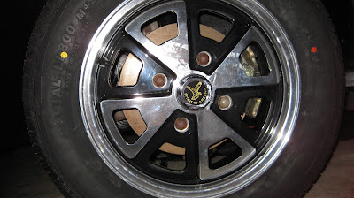
But I have had the brand new mag wheels that I traded the engine for mounted on the new Classic All Season 165/80/15 tires I purchased from Tire Kingdom today for $369.28 thank you. I was so excited, I could hardly wait to get them home and mounted on the vehicle and boy do they make the car look good especially after sitting atop the sawhorses for almost two years.


Here's a side view. It almost looks like the rear end is jacked up off the ground but I assure you it is not. It's the new 180lb springs over the new Boge shock absorbers that make it look that way.


The aluminum mag wheels sat for so long in the garage that a couple of them pitted a little. But they still look good. I know the lug nuts look rusted but come on, they are the original 35 year old lugs. I'll splurge and buy some new chrome lugs once I get closer to getting on the road.


I'm not going to promise but I will seriously try to mount the transmission and motor this weekend. It may be all I can do to just mount the clutch and adaptor plate to the motor. I'll need to rent an engine hoist so I can mate the motor/adaptor/clutch assembly to the transmission. And then using a jack with a transmssion mount, jack the entire assembly up under the rear of the car and bolt it in place. Ooh boy, lots of work. More in my next blog. Caio.

Sunday, October 24, 2010

Contactor and Control Box Installation

October 24, 2010 - It's been 12 weeks since my last post, way too long if I'm to finish this project by 1st quarter 2011. I've been waiting on ordered parts like the contactor from EVSource which had been back ordered.

But I finally took the opportunity to install the contactor and control box in the engine compartment affectionately known as the "hellhole". The contactor is an Albright SW200 knock-off by Chinese manufacturer Nanfeng cost $88 from EVSource. According to the EVSource web site: "This contactor is rated at 250 amps continuous and 96VDC. It has a 12V coil, and comes with magnetic blowouts. A bracket and screws are included with the contactor. It has almost the identical size, dimensions, coil current draw, and internal spring force as the Albright SW-200 contactor." This contactor is pretty big at almost 7" in height and weighs about 3 lbs.

Here's a side view of the contactor:


And front view:


The control box from EVHelp is a basic logic circuit that takes as input: 1) switched power, 2) parking brake ground, and 3) common terminal of potbox microswitch (result of brake being pressed). This ensures that the contactor won't close unless the key switch is on, parking is off, and brake has been pressed.

Here's the control box:


I'm using two 8-position European style terminal blocks, one for 12-volt connections, and one for high-voltage (120V) connections. Here's the terminal block:


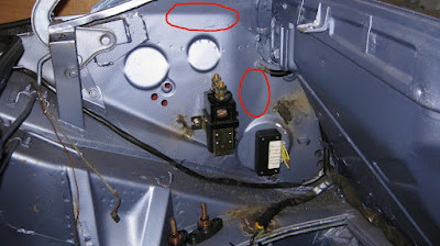
I pressed 1/4" rivnuts into the interior wall and used 1/4" bolts to attach the contactor into place. I also used 6-32X rivnuts and 1/2" machine screws to anchor the control box into place. Here's some shots of the contactor and control box installed:


I'll mount the terminal blocks where the red circles are and hopefully wire-up the 12-volt control circuit some time this week or next weekend.

Sunday, August 1, 2010

Brake Calipers Installed

August 1, 2010 - It's been three weeks since my last post. Been kind of lazy lately. However, I have been designing the mid-engine compartment wiring over the last couple of weeks. As I have been following ElectroAutomotive's VoltsPorsche installation manual, my design is beginning to differ somewhat as I am going to incorporate Metric Mind's EVision metering system, see my June 17th post.

Today, though, I have been able to install both front and rear calipers. I have updated the front calipers with 1981 BMW 320i calipers which supply almost 50% more brake pad surface area. The BMW calipers are a good bit larger but fit almost perfectly. I purchased a pair from someone on 914world.com for about $200 over a year ago. They had already performed the slight machining required and refurbished them too.

Here's the left front:


And the right front:


And of course, don't forget the brake hoses.

Here's the new left front brake hose:


And the new right front brake hose:


I refusrbished the rear brake calipers myself with a kit from Automotion or Pelican Parts can't remember. I did use the tech notes from Pelican Parts though and it was extremely helpful. I used a copper colored high-temperature spray paint from Lowe's for about $8/can, brake caliper paint was quite expensive about $30-40 if I remember correctly. Oh yeah, forgot to mention I installed the rear rotors too. Believe it or not, they're held in place by two machines screws each.

Here's the right rear caliper:


And the new right rear brake hose:


Here's the left rear caliper:


And the new left rear brake hose:


I have also refurbished the rear swaybar. I wirebrushed it, rust encapsulated it, and then spray painted it with black enamel. I did the same to the swaybar links too.

Here's the rear swaybar and right link:


And the rear swaybar and left link:


Closeup of left rear swaybar link and new link bushings:


And right rear swaybar link and new link bushings:


Here's a brand new rear swaybar bushing:


And a full view of the rear swaybar and links:


I just need to find the rear caliper brake fittings to the brake hose and install them. Also need to install the front fittings from the master cylinder along with the brake reservoir and fittings to the master cylinder. More next weekend. Caio!