Sunday, October 24, 2010

Contactor and Control Box Installation

October 24, 2010 - It's been 12 weeks since my last post, way too long if I'm to finish this project by 1st quarter 2011. I've been waiting on ordered parts like the contactor from EVSource which had been back ordered.

But I finally took the opportunity to install the contactor and control box in the engine compartment affectionately known as the "hellhole". The contactor is an Albright SW200 knock-off by Chinese manufacturer Nanfeng cost $88 from EVSource. According to the EVSource web site: "This contactor is rated at 250 amps continuous and 96VDC. It has a 12V coil, and comes with magnetic blowouts. A bracket and screws are included with the contactor. It has almost the identical size, dimensions, coil current draw, and internal spring force as the Albright SW-200 contactor." This contactor is pretty big at almost 7" in height and weighs about 3 lbs.

Here's a side view of the contactor:


And front view:


The control box from EVHelp is a basic logic circuit that takes as input: 1) switched power, 2) parking brake ground, and 3) common terminal of potbox microswitch (result of brake being pressed). This ensures that the contactor won't close unless the key switch is on, parking is off, and brake has been pressed.

Here's the control box:


I'm using two 8-position European style terminal blocks, one for 12-volt connections, and one for high-voltage (120V) connections. Here's the terminal block:


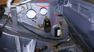
I pressed 1/4" rivnuts into the interior wall and used 1/4" bolts to attach the contactor into place. I also used 6-32X rivnuts and 1/2" machine screws to anchor the control box into place. Here's some shots of the contactor and control box installed:


I'll mount the terminal blocks where the red circles are and hopefully wire-up the 12-volt control circuit some time this week or next weekend.

Sunday, August 1, 2010

Brake Calipers Installed

August 1, 2010 - It's been three weeks since my last post. Been kind of lazy lately. However, I have been designing the mid-engine compartment wiring over the last couple of weeks. As I have been following ElectroAutomotive's VoltsPorsche installation manual, my design is beginning to differ somewhat as I am going to incorporate Metric Mind's EVision metering system, see my June 17th post.

Today, though, I have been able to install both front and rear calipers. I have updated the front calipers with 1981 BMW 320i calipers which supply almost 50% more brake pad surface area. The BMW calipers are a good bit larger but fit almost perfectly. I purchased a pair from someone on 914world.com for about $200 over a year ago. They had already performed the slight machining required and refurbished them too.

Here's the left front:


And the right front:


And of course, don't forget the brake hoses.

Here's the new left front brake hose:


And the new right front brake hose:


I refusrbished the rear brake calipers myself with a kit from Automotion or Pelican Parts can't remember. I did use the tech notes from Pelican Parts though and it was extremely helpful. I used a copper colored high-temperature spray paint from Lowe's for about $8/can, brake caliper paint was quite expensive about $30-40 if I remember correctly. Oh yeah, forgot to mention I installed the rear rotors too. Believe it or not, they're held in place by two machines screws each.

Here's the right rear caliper:


And the new right rear brake hose:


Here's the left rear caliper:


And the new left rear brake hose:


I have also refurbished the rear swaybar. I wirebrushed it, rust encapsulated it, and then spray painted it with black enamel. I did the same to the swaybar links too.

Here's the rear swaybar and right link:


And the rear swaybar and left link:


Closeup of left rear swaybar link and new link bushings:


And right rear swaybar link and new link bushings:


Here's a brand new rear swaybar bushing:


And a full view of the rear swaybar and links:


I just need to find the rear caliper brake fittings to the brake hose and install them. Also need to install the front fittings from the master cylinder along with the brake reservoir and fittings to the master cylinder. More next weekend. Caio!

Sunday, July 11, 2010

EV Controller Installed

July 11, 2010 - I've installed the first EV Component, the controller. Woohoo!! This is a major milestone as I've been in restoration mode for almost two years. The controller is a proprietary design by Mark Hazen of EVHelp.com. Mark has a patent-pending on his design where instead of a straight bus of MOSFETs, they are arranged in a circle he calls the "Power Wheel". This arrangement allows the power to flow uniformly and heat to be transferred in the same way.

Due to the size of the controller, mounting plate, and heatsink, I had to alter the firewall by cutting out a piece of the shelf. I drilled a couple of holes at the bottom of the firewall and installed 1/4" rivnuts.


I had never heard of a rivnut before but I'm doing the majority of my install from ElectroAutomotive's VoltsPorsche installation manual and Mike Brown uses them whenever he can't get access to both sides of a mount point. I got my Rivnut kit from Harbor Freight for about $15.


Here's one of the bottom mount points with rivnut installed, both of them required rivnuts as I couldn't get access to the other side of the firewall.


Here's a shot of the controller installed, nicely snuggled into the lower right portion of the hellhole firewall. You can clearly see the controller terminals (B+, B-, and M-) and the control terminal which accepts connections from the Control Box. Mark's controller comes with a control box of his design which ensures that the parking brake is off, foot is off the accelerator, and foot is on the brake pedal before power is supplied to the controller.


Here's a closeup shot of the left lower mount point with standoff. I may have to use longer standoffs and bolts to allow enough room for air to flow between the firewall and heatsink. But I remember Mark saying he added the heatsink to ensure adequate cooling of the MOSFETs.


And a shot of the top of the controller showing the upper mount points and standoffs. I was able to install the bolts from the cockpit and use nylock nuts to fasten the controller's mount plate.


Another shot of the top of the controller but looking down into the hellhole from the outside.


And finally, a great shot of the entire firewall showing the nestled controller. You can also see the rear battery rack suspension mount posts mounted onto the control arm pivots aka suspension ears. I test fit the battery rack onto the mount posts to make sure that the controller would not interfere with the rack installation later. It's a tight fit but it works.


I'm going to try and mount the potbox assembly to the lower left portion of the firewall next weekend. Caio!

Monday, July 5, 2010

Mounting the rear wheel hubs

July 5, 2010 - It's been a nice long 3-day weekend, mostly rainy here in FL, and sad to say but I don't have a lot of progress to show for it. I have been able to mount the rear wheel hubs back into the trailing arms. As the wheel bearings have already been pressed into the trailing arms and the trailing arms have already been mounted onto the frame, pressing the hubs into the wheel bearings posed somewhat of a problem. Alas, the solution was documented on a 914world.com forum, the Garage.

The solution was a straight forward and low-tech. Use an allthread of appropriate length and width, and washers and nuts that fit the allthread. Sandwich the trailing arm/bearing and wheel hub with the nuts and washers, and then slowly draw the hub into the bearing by tightening the nut/washers on the outside of the hub. Upon inspection of the setup, it was obvious that I would need a couple of pieces of 2x4, one inside the inner bearing well, and one outside the hub.

So here's a pic of the required components. The block in the foreground was cut to fit into the inner trailing arm bearing well where the driveshaft connected to the cv joint is usually located. The vertical 2x4 acts as a stabilizer because the allthread is approximately 3ft long. The allthread is 1/2in x 3ft.


I needed 2 1/2in nuts, 2 1/2in washers, and 2 3/4in washers.


Here's the allthread and inner block located just inside the trailing arm bearing well. The vertical 2x4 stabilizer keeps the allthread centered and from damaging the bearing.


Now here's the setup with the hub already seated into the bearing. A couple of things the forum recommeded was to freeze the hubs and coat the inside of the bearings and the outside of the hub race with grease. The frozen hub is then just pushed onto the bearing and the outer block, washers, and nut mounted. The nut is tightened relatively easily with a wrench and the hub drawn into the bearing due to the hub metal having contracted with the cold.


Here's a three-quarter view of the hub fully seated into the bearing. The hub really was easily pressed into the bearing after being frozen. I was quite surprised at how easy it went in considering nothing has been easy on this car.


And finally, the hub fully seated inside the bearing.


Next step is to mount the rear rotors. Then mount the calipers and brake pads on both front and rear rotors. Then bleed the brake system and ensure that the brakes actually work.

Friday, June 18, 2010

Front Suspension Installed

June 18, 2010 - After most of last weekend 6/12-6/13 and this evening, I was able to wrap up re-installing the front suspension. Whew! What a job that was.

About a year ago, I spent about 2 weekends wirebrushing and sanding the control arms, auxillary support carrier, and shock aborber struts. I sprayed them with Eastwood's Rust Encapsulator and then spray painted them with black enamel paint.

Of course, the really hard part was getting the old rubber bushings off of the control arms. With the aid of my neighbor Gene aka the Gas Doctor, we heated the control arms with a propane torch just enough to get the rubber soft and was then able to pry the control arm bushing sleeves off of the control arms.

I ordered new polygraphite front control arm bushings from Pelican Parts (a set of 4 for $20) and then proceeded to install them. That was no easy task in itself but my neighbor Tony helped me to brute force them on and into position. Did I say that it's really good to have helping neighbors? I couldn't do all of these things without my neighbors' help. Here's the bushings:


And here's how they fit on:


I purchased a brand new pair of Bilstein front struts from PartsGeek for about $230 over a year ago. I also purchased a set of turbo tie rods from PartsGeek for about $150 a little later. I really don't have a lot of money but if you purchase these items on a monthly basis over a year's period or more, it really is a lot less of a strain on your budget. Oh yeah, I almost forgot the 23mm SwayAway torsion bars from Don's Sport Vehicle for about $230 but it took them 3-4 months to get them to me.

Here's the left turbo tie rod installed:


And the right turbo tie rod:


The ball joints were about $70/piece for a total of $140 from PartsGeek; again, another monthly expense from over a year ago. I had to lower the control arm/carrier assembly after bolting it in place in order to install the ball joints. Once I got the ball joints in place at the bottom of the struts, I also had to lower the struts and slowly raised the control arm/carrier assembly to fit the ball joints into the control arm and then tighten the grooved nuts over the bottom of the ball joints afixing them and the struts to the control arms. Here's the left ball joint:


And right ball joint:


After I got the ball joints installed, I had to slowly raise the control arm/carrier/strut assembly until the top strut bolts fit thru the front shock tower holes. I added the tab washers and locking nuts to the top of the struts and tightened them down.

Both turbo tie rod and ball joint attached to the right strut:


And the left strut:


Here's the right control arm front bushing and torsion bar:


And the left control arm front bushing and torsion bar:


I just need to glue the torsion bar caps back into place and bolt the bushing sleeves to the bottom of the frame.

Thursday, June 17, 2010

Evision and LiFePO4 in my future

June 17, 2010 - I've finally made the mental decision to go with LiFePO4 (lithium iron phosphate) batteries instead of lead acid. The decision was a long and difficult one but after carefully weighing the facts, it was obvious that lithium was the intelligent way to go.

The cost of 20 US Battery US-2200 232AH batteries is approx $2600, would weigh 1240 lbs, provide 120V traction pack, may last 3-5 years, and would probably only get a range of perhaps 40-50 miles on a single charge with moderate driving.

The cost of 40 Thundersky TS-LFP200AHA batteries is approx $10000, would weigh 640 lbs, provide a 128V traction pack, may last 8-13 years, and would probably get a range of 80-100 miles on a single charge with moderate driving. Thundersky specs >= 3000 charge cycles for 80% DOD and >= 5000 charge cycles for 70% DOD.

What's amazing about the lithium batteries is that they have an energy density of almost 5 times that of lead acid batteries. That means that a lithium battery stores 5 times the power per kilogram of weight than lead acid and 2 times as much as NiMH.

There are two different form factor 200AH batteries from Thundersky. 4 cells will constitute a 12.8 battery pack with 10 batteries supplying 128V. The Type A packs will fit into the polypropylene battery boxes quite nicely. 5 packs will fit into the front box and 5 will also fit into the engine box both boxes will have room to spare. The Type B packs are a good bit larger than the Type A but will fit into the racks for the front and engine compartments.

Thundersky TS-LFP200AHA Type A is 11in H x 7-1/4in W x 2-3/4in L


Thundersky TS-LFP200AHA Type B is much larger at 10" H x 14-1/4" W x 2-1/4" L


Considering the overall cost of the restoration and conversion, even though the lithium batteries are 4 times the cost of lead acid batteries, the lithium batteries will provide the conversion with a quality traction pack that will make it comparable in range to that of the new Nissan Leaf. The lithium pack will also allow me the opportunity to drive a round-trip work commute without having to charge at work. The addtional power will allow me to install an air-conditioning system that is much needed here in FL.

To ensure that extra precaution is taken to protect my significant investment in lithium technology, I have decided to purchase an EVision system from Metric Mind. The main purpose of the EVision is to monitor the State of Charge and ensure that I don't exceed an 80% DOD.

Here's the EVision displayed in both color schemes. I like the blue and white display.


The EVision should barely fit into the Porsche's fuel gauge housing. The housing is about 95mm in diameter whereas the Evision is about 73mm in diameter and PC board is 86mm wide. Here's the fuel gauge:


And the EVision In-dash display:


I'm still trying to find out what the cost of the EVision is. The Metric Mind website currently says price is TBD but I seem to remember looking at the site about a year ago and thought it said $600-700 plus you need $100 worth of shunts, so, I'm going to budget about $1000.

Finally got a response from Victor Tikhonov of Metric Mind but he replied saying that pricing was still not available but that it shouldn't be more than $900. So my budget estimate was right on the mark.