Wednesday, April 27, 2011

Wiring Diagrams

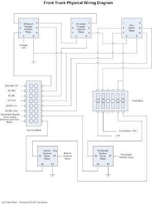
April 27, 2011 - I thought that since I'm wiring up the car it would be a good idea to take my pencil diagrams and convert them to Visios and publish them. Its not so much for review as it is to share with others that may be struggling with their designs. I do have ElectroAuto's installation manual which helps a great deal but my design is different enough and the engineer in me needs to document it so that I don't make any mistakes when wiring it all up.

There are three basic diagrams:

1 - High Voltage Physical Wiring Diagram
2 - Engine Compartment Wiring Diagram
3 - Front Trunk Compartment Wiring Diagram

Here's the High Voltage Physical Wiring Diagram:


And the Engine Compartment Wiring Diagram:


And finally the Front Trunk Compartment Wiring Diagram:


Sunday, April 24, 2011

Potbox Part Deaux

April 24, 2011 - Another week has passed, and another 14-18 hours worth of work has been performed. On Fri, I received the Curtis PB-6 potbox which looks like it was shipped from KTA out of Ramona, CA. I have to say that this piece of gear is exceptionally well made. The construction of the box itself and the arm is of high quality material. The microswitch is definitely industrial grade and potentiometer looks to be of highgrade electronics as well.

Closer inspection revealed that there is very little difference between the potbox that Mark Hazen of EVHelp made for my controller and this Curtis PB-6. In fact, the only two differences were the potentiometer that was in the Curtis was a 0-5KOhm while the one in Mark's potbox was 0-2KOhm wired the opposite 2KOhm-0 and the diode to prevent the microswitch contacts from arcing from the opening of the contactor coil. So I replaced the potentiometer on the Curtis with a reverse wired 0-2KOhm and voila, it works just like the one Mark fabricated.

Here's a close up of the Curtis potbox mounted on an aluminum mount I fabricated with the help of two of my neighbors, Gene and Tony.


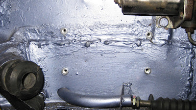
To mount the fabricated aluminum mount onto the firewall, I drilled four 3/8" holes and installed four 1/4" Rivnuts. Here's a shot of the installation site with the rivnuts freshly installed:


I then used 1/4" bolts to fasten the potbox mounts to the Rivnuts. I have to say, I am much happier with this arrangement than I was with the EVHelp's potbox mounted in the aluminum box.


Here's a great shot of the entire lower firewall showing the potbox on the left, emergency breaker in the center, and controller on the right. You can definitely see that the controller bottom is flush with the bottom of the firewall, thus the need to add a ramair scoop.


Next, I moved on to increase the offset between the firewall and the controller that will allow air to flow over and hopefully cool the heatsink fins. I will add a ramair scoop to the bottom of the controller that will extended below the firewall and redirect oncoming air into the new formed cooling cavity. I increased the offset from 1" to 2-1/2" which created a cooling channel of 1-1/2". Here's a shot from the left side of the controller:


Here's a shot from the bottom of the car looking up:


And finally a shot from the top of the controller looking down:


What's left is to wire up a few more things, probably a dozen wires or so and cable up the emergency breaker before I mount the motor and transaxle.

Thursday, April 21, 2011

Pot box issue resolved

April 20, 2011 - Last time I blogged about how the pot box from Mark Hazen at EVHelp wasn't working out with my throttle cable and how I had ordered a Curtis PB-6 to replace it. A couple of days ago Mark e-mailed me to see how things were going with the conversion and I relayed to him the problem I was having and how I was going to solve it. It's a good thing Mark and I had the mail exchange because I found out that the Curtis pot box won't work. Here is what Mark had to say about that: "The Curtis PB-6 throttle control will NOT work on my controller. It will cause the controller to start at full throttle with a huge surge in power that will jerk your head back and perhaps destroy the controller and cause an accident in your garage."

Hoo boy, what a catastrpohe waiting to happen. Mark pointed out that the Ohm range in his pot box was backward (2KOhm - 0Ohm) and different than the Curtis PB-6 (0Ohm - 5KOhm) and he does make reference to the range in his installation manual but does not note that his controller is incompatible with the Curtis pot box.

Anyhow, he recommended that I lower the position of the cable attach point on the pot box arm to accomodate the short throw of my throttle cable. It took two tries but I finally got it right. What didn't help was the fact that the throttle cable was also partially binding on the clutch cable assembly preventing full throw of the cable. Once I figured out where it was binding and freed it up, the cable travelled full distance and freely.

I also had to extend the offset on the pot box from 1-1/2" to 2-1/2" to allow this additional length. Once I had the new offset mounted and attached the cable, when I pressed the accelerator pedal fully, I got full deflection on the pot box. And yes, I plan to fabricate a thicker and stronger offset than the thin aluminum one shown. Whew!! Anyone wanna buy a brand new Curtis PB-6 when I get it? $80 plus shipping.

Here's the pot box at zero deflection:


And at full deflection:


April 21, 2011 - Update to resolution. OK, my boss Adam Kreuger and EVHelp's Mark Hazen must be smarter than me because when they saw my offset they both just kind of snickered and said "get rid off the offset and just cut the cable", independently of course. DOH!!!! Thank goodness for out of the box thinkers. Of course, I soldered the end of the cable so it won't fray. I'm worried that the cable may slip in barrel connector so I will also solder the cable area that is being clamped down on for extra hold strength.

So here's a pic of the zero offset zero deflection:


And another at full deflection:


Now just to mount the pot box on the firewall. Oh, and Mark also lamented that I should pull the controller off of the firewall to allow air flow. I'm guessing 1-2 inches should suffice plus the addition of a ram air scoop that dips below the firewall should force enough air over the cooling fins to keep it from over heating. He also mentioned that I may want to look at adding some sort of high volume blower that blows lengthwise over the heatsink fins.

Monday, April 18, 2011

Low-Voltage Wiring Installation

April 17, 2011 - Believe it or not, I continue to make forward progress. I still haven't mounted the motor/transaxle but with good reason. For this blog entry, I have started wiring the low-voltage circuits in the engine compartment affectionately known as the "hell-hole".

Now, the reason I haven't mounted the motor/transaxle assembly into the engine compartment is that the original throttle cable I purchased from Pelican Parts became defective last weekend. From what I understand, these Gem cables are notorius for breaking. So I ordered another Gem and a higher-priced Terri cable from Pelican Parts. Pelican Parts is an awesome supplier. They keep you well-informed during the entire order processing flow via e-mail, and ship the merchandise ASAP.

So I received the new cables mid last week and immediately installed the Terri cable which I really like over the Gem cable. I hooked it up to the custom pot box from Mark Hazen at EVHelp.com (it came with the controller I purchased from him) but to my dismay, when the accelerator is pushed all the way to the floor, the pot box lever only defleected about 1/4 way. Mark's pot box doesn't start registering the pot changes until the final quarter or third of the defleection. Hmmm, this won't do. Here's a pic of the pot box enclosed in a nice aluminum box I purchased from MCM Electronics for $15.


Notice the aluminum extension on the left. I needed to extend the length of the enclosure as the cable was too long and no effective way to shorten it. Soooo, I've ordered a standard Curtis PB-6 from Electric Vehicles of Washington for $80, the cheapeast I could find without getting a knock-off from China. It looks the the deflection of a common Curtis PB-6 is about half or less than that of Mark's pot box.

Next up is the installation of the emergency breaker. I got this 120VDC Airpax breaker brand new off of eBay for a very nice price. It fits very nicely onto the firewall. Obviously, I haven't wired it up to the 2/0 cables yet but that part is coming soon enough. I may go ahead and start the 2/0 cabling before I mount the motor/transaxle assembly. It will be that much more difficult to do so after its mounted. Here's a closeup of the breaker. The wire attached to the breaker switch is the heater flap cable which is connected to a lever located very close to the stick shift. Easily accessible if motor ever attempts to runaway for whatever reason.


And another shot showing the breaker in geographical relation to the controller.


At last, I spent a lot of time on a mechanic's crawler getting in and out the the hellhole. What a PITA. But I was able to get most of the low-voltage wiring completed. I just need to hookup less than a dozen wires or so to complete the task. You can also see the fuse block at the bottom left that will contain a Ferraz Shawmut fast-acting amp-trap fuse. I haven't figured out where to mount it yet but am leaning toward the shelf that is at a 45 degree angle to where it currently sits. The negative end of the front pack will connect to one end of the fuse and the positive end of the rear pack will connect to the other end.


In this picture you can see the relay (left of the main contactor) I've added for the Motor Temp switch that comes with the Warp9 and is normally closed but opens when over temp is reached. I'm using the relay to complete the circuit to ground to the Oil Pressure indicator (red) on the Fuel Gauge. It hasn't been wired up yet.
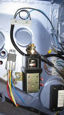


Here's a closeup of the control box from EVHelp which has 3 relays built into it to prevent an improper startup sequence, mainly, 1) parking break off, 2) foot off accelerator, and 3) foot on brake.


Here's a closeup of terminal block #2. The in-line fuse that is resting on one of the contactor high-voltage terminals comes from the control box and will be wired up to pack side with a ring connector.

Wednesday, April 6, 2011

Mounting Issue Resolved

April 6, 2011 - I was able to resolve the motor mounting issue by having additional holes drilled. Apparently, whoever EletricAutomotive used to fabricate the motor mount, they drilled the holes backwards or in a mirrored state. I measured and marked mirrored bolt holes into the motor mount and took it to Dick Warren's Machine Works here in Tampa where they drilled the new holes for $5. As you can see, the holes aligned perfectly.


I purschased new tranmission mounts from Pelican Parts for $23/each, 2 required along with new angled speedometer drive for $97 and new backup light switch for $85. I also ordered a new transmission ground strap for $14 and a gallon of Swepco transmission fluid for $54. Altogther, the order amount was about $300. Ouch, ouch, and did I say ouch?


So, only things left to do before mounting the motor/transaxle assembly is to mount the pot box and emergency breaker and wire up the control circuits. A little more work but hopefully something I can do over the next several days so I can mount the assembly this weekend.